All posts by admin

Add custom scripts

Note: Google Drive links may not work or might be expired. You can find the scripts here

Tutorial no 11

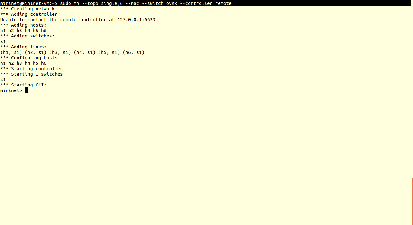
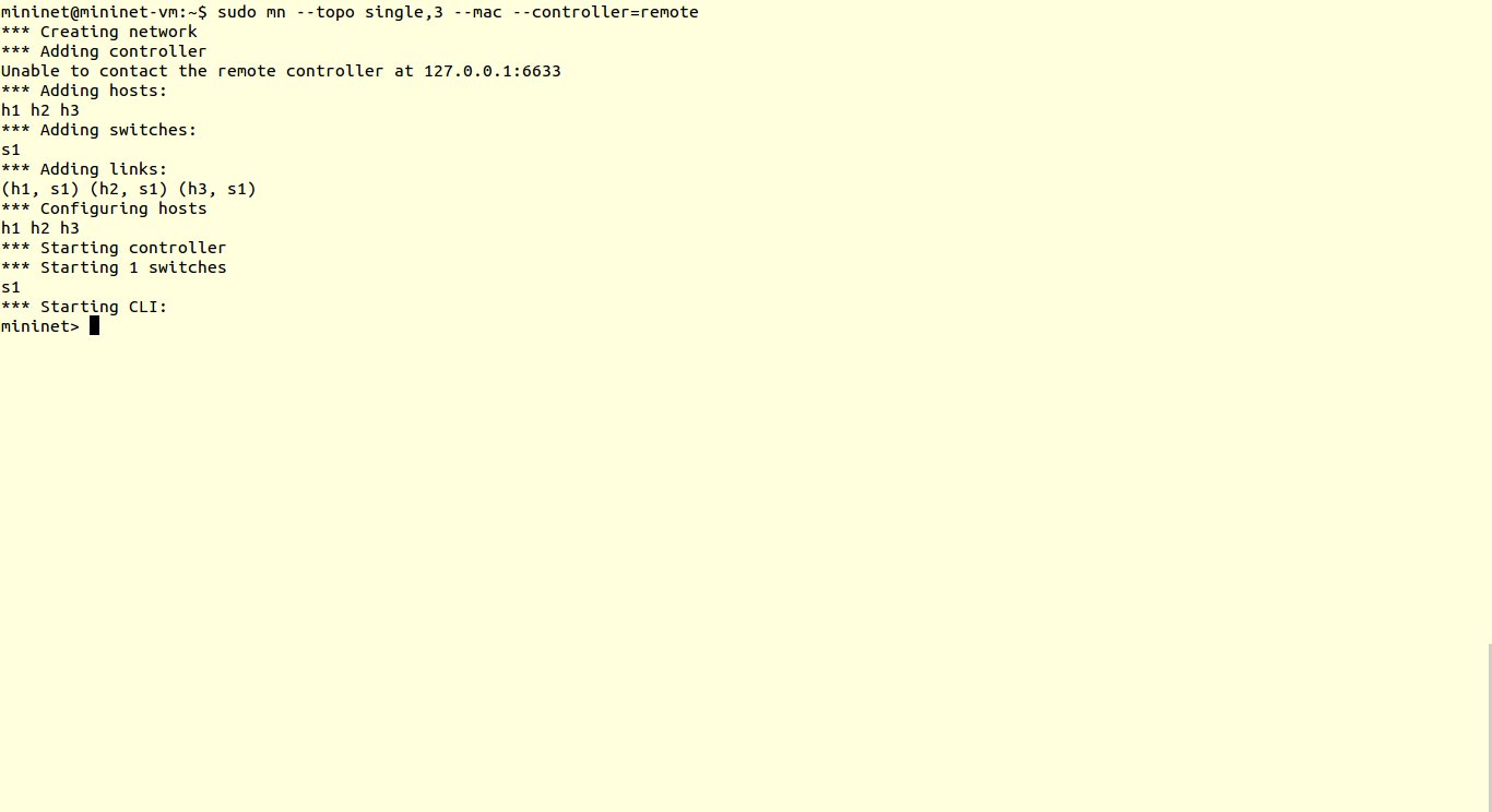
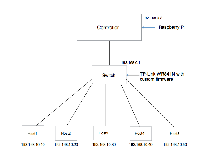
                               So, in all the tutorials we covered before, we have used default controller scripts & default topologies. In this tutorial we are going to design our custom topology and custom controller scripts.

                                 You will find this tutorial very interesting, because till now we have created topologies in Command Line Interface ofMininet. And here we have Graphical Interface. We will use cloud application called VND (Virtual Network Descriptor) to create topology and controller script. This VND tool is developed by Ramon Fontes, Federal Institute of Bahia, Brasil and available on

www.ramonfontes.com/vnd                                                                                                                   (Note:- You should have updated flash player in your system to work with VND)

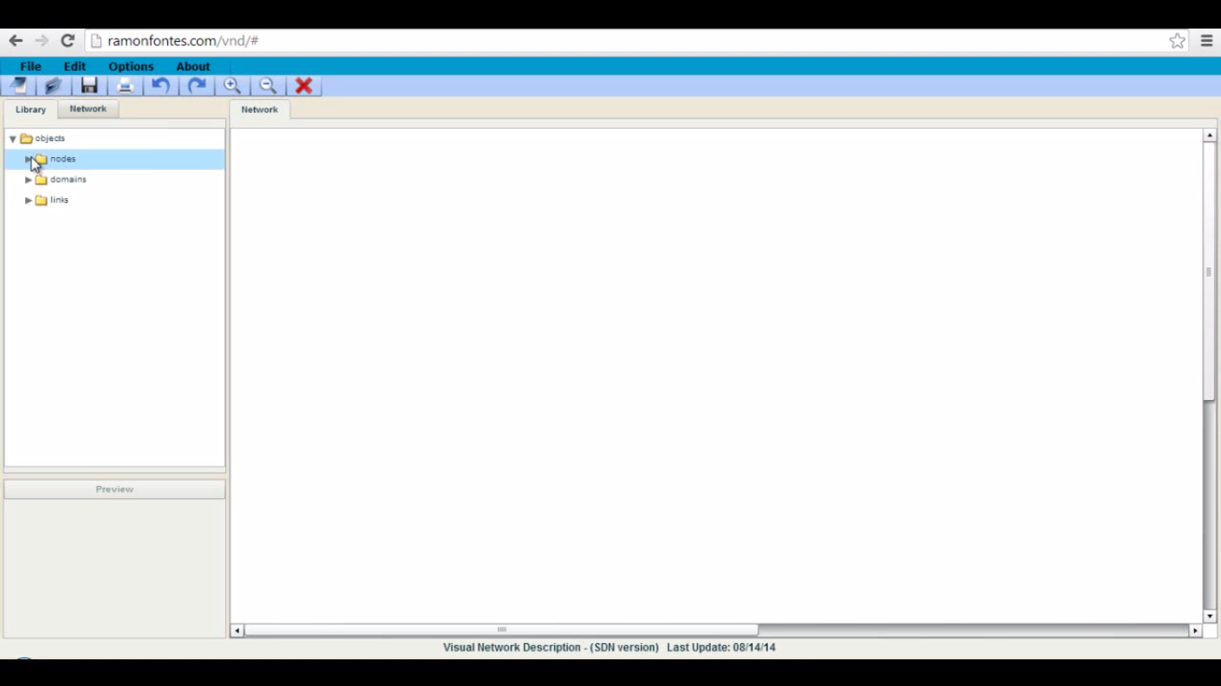
1) Visit above link to getting started with VND.

1

2)To create topology, select hosts, OpenFlow switch and OpenFlow controller. Use Ethernet links to connect hosts.

2

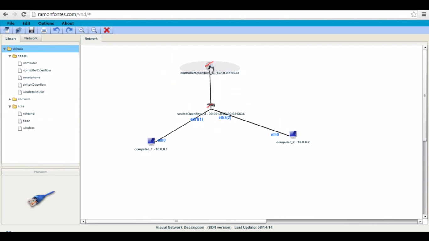
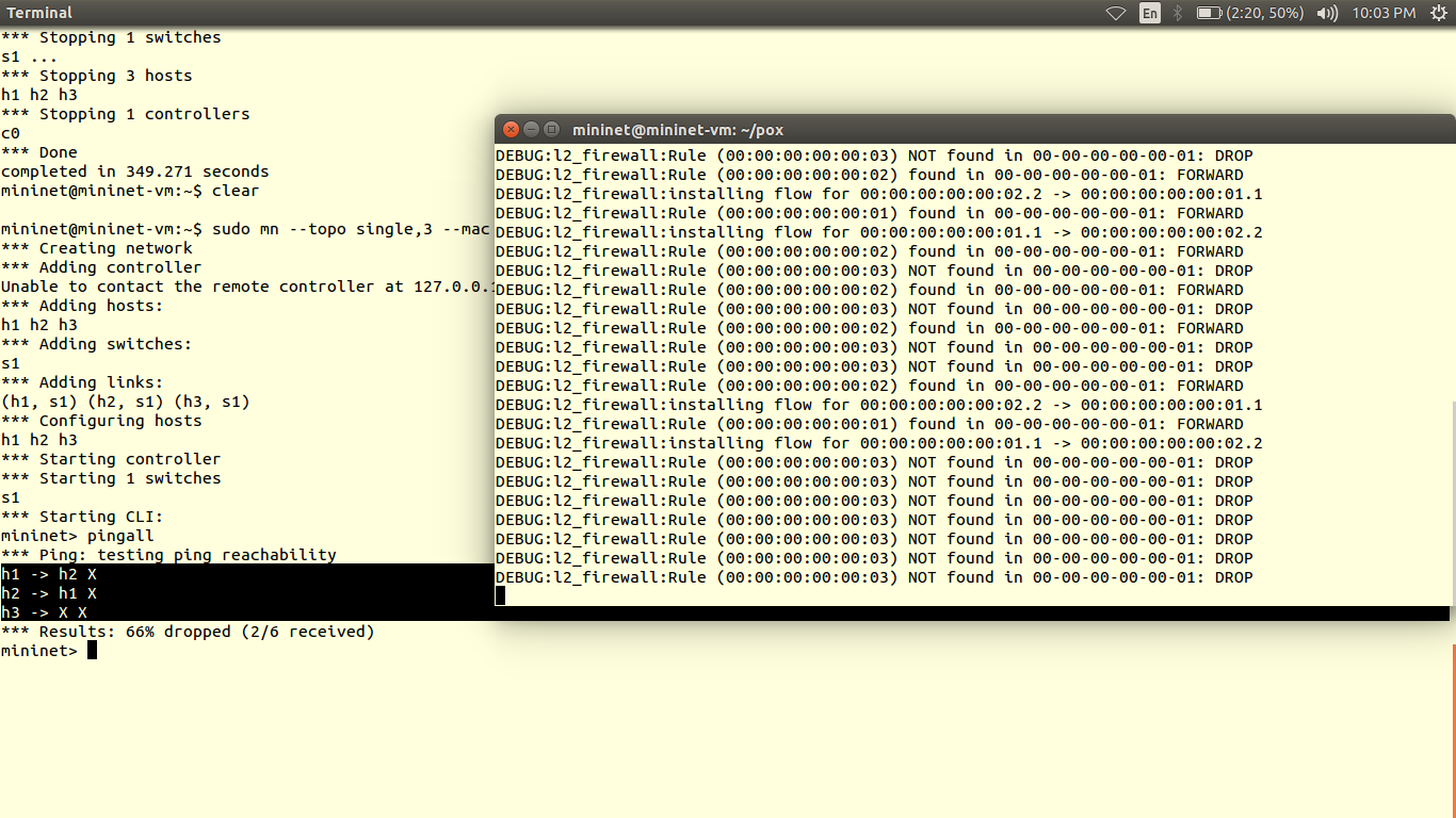
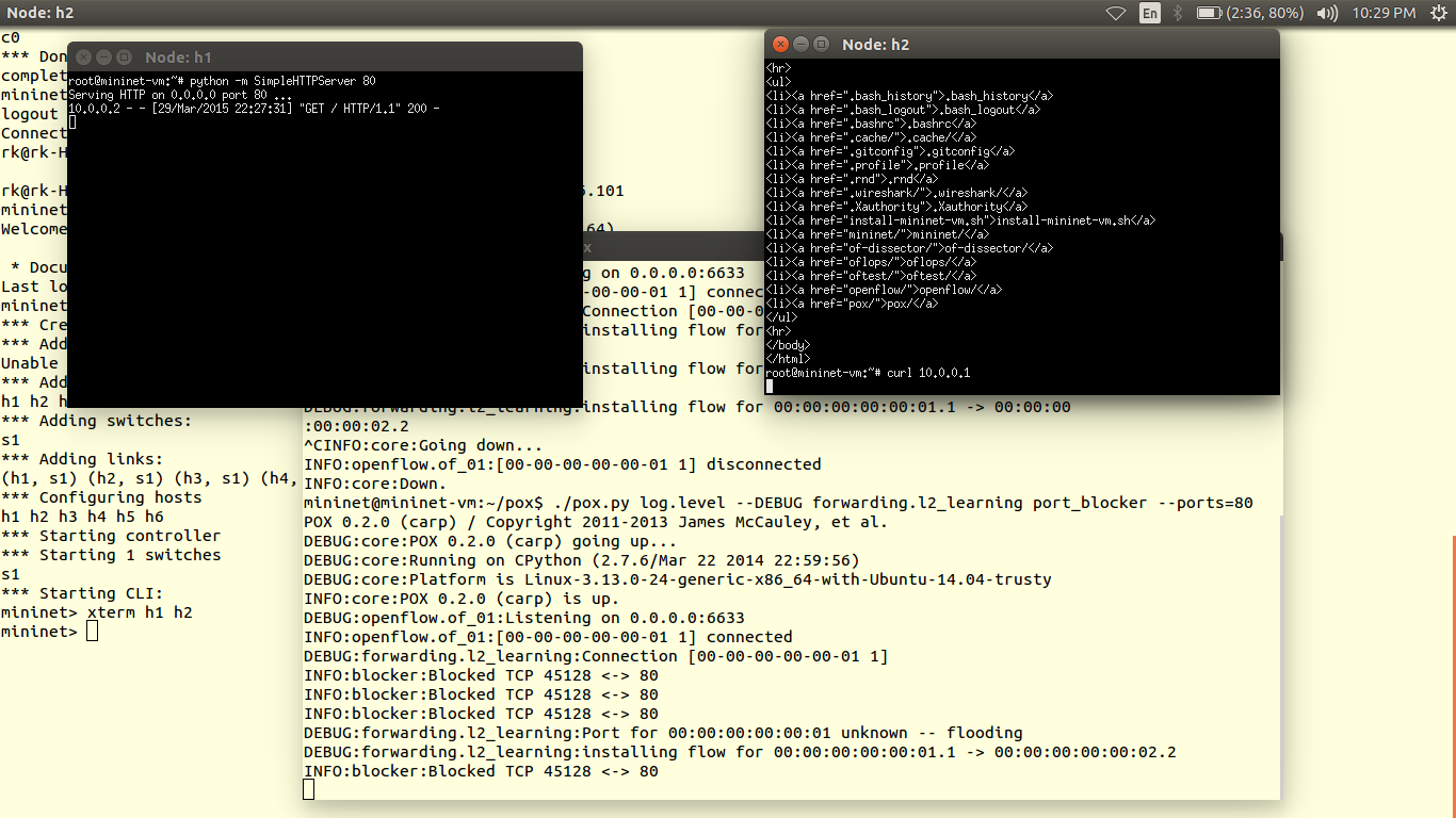
3) After that lets focus on controller configuration. Now we will define simple flow rule for host1 and host2 traffic.

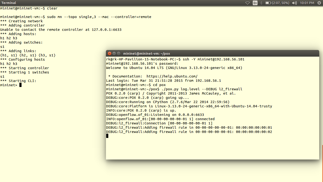
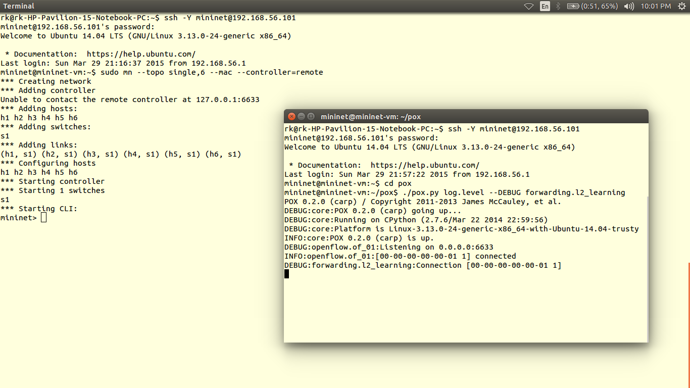
Select controller POX

Ingress port=1, Output=2      # packets coming from port 1 are forwarded to port 2                  Ingress port=2, Output=1      # packets coming from port 2 are forwarded to port 1

3

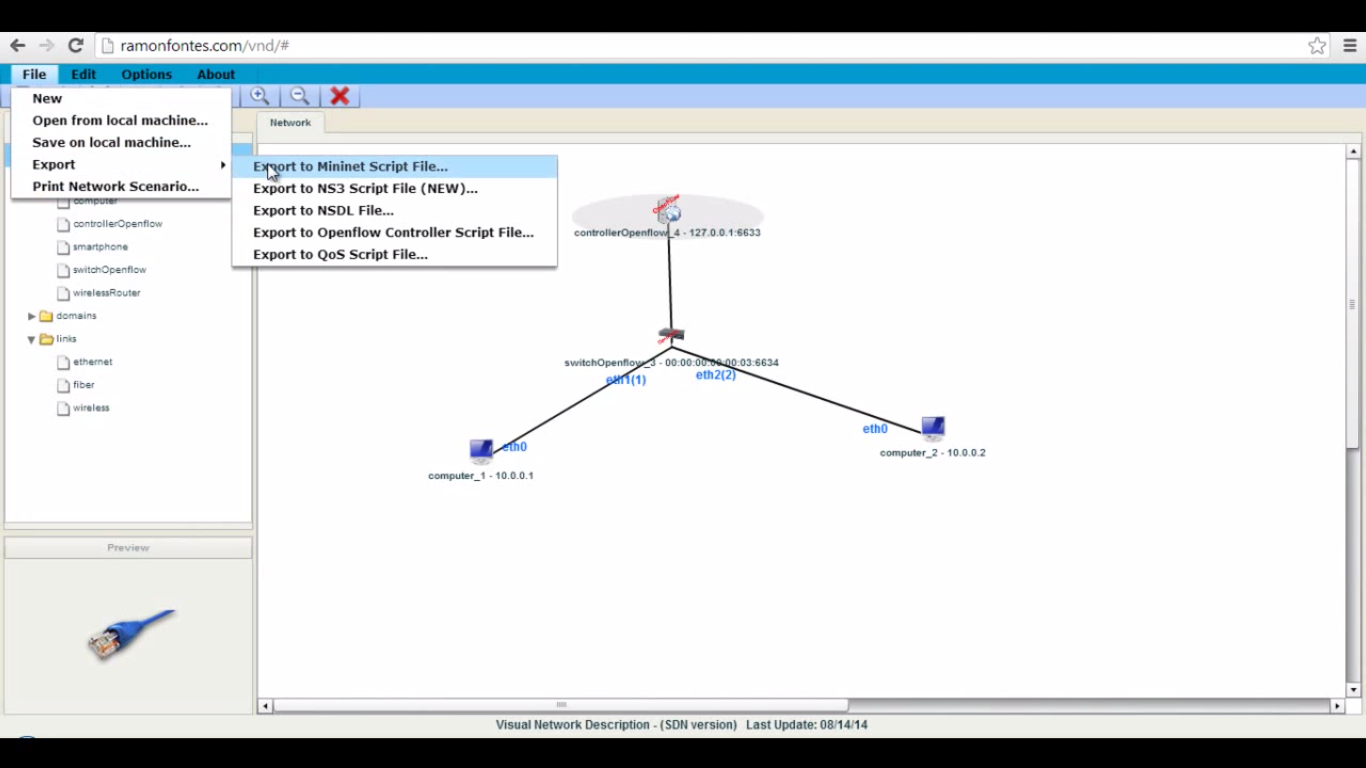
4) After all configurations, download the both topology and controller scripts.

7

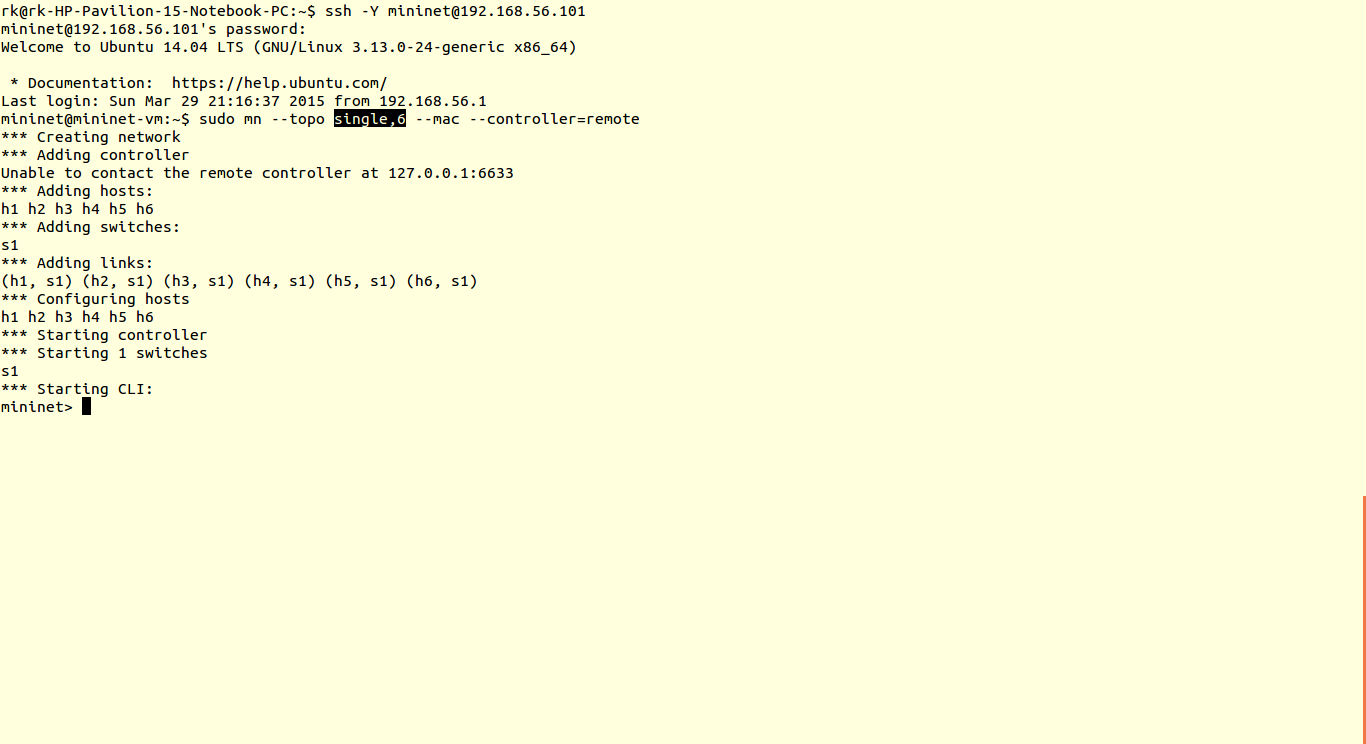
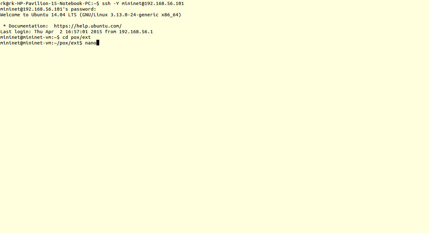
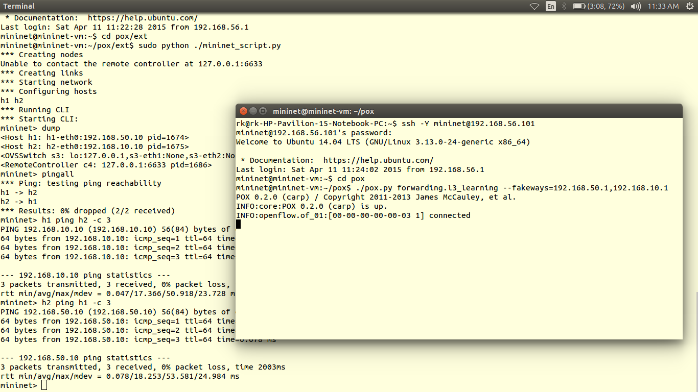
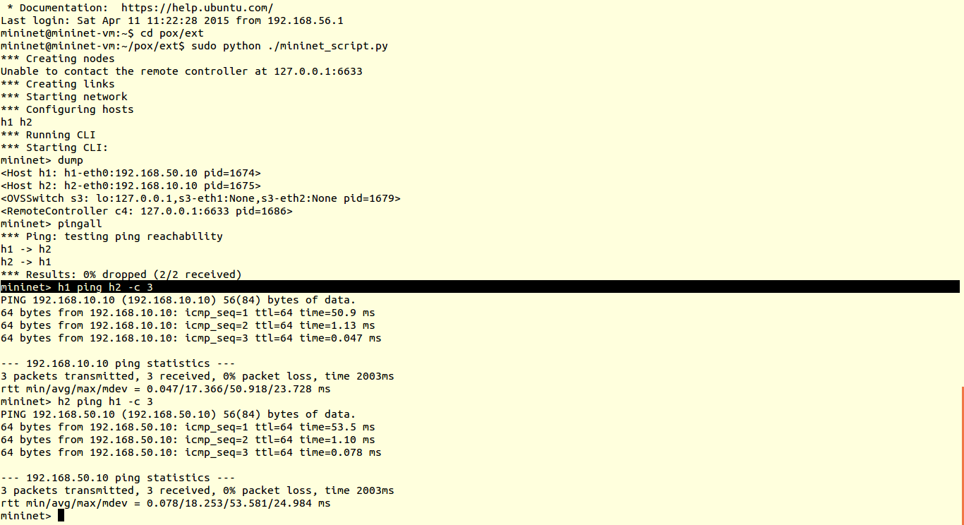
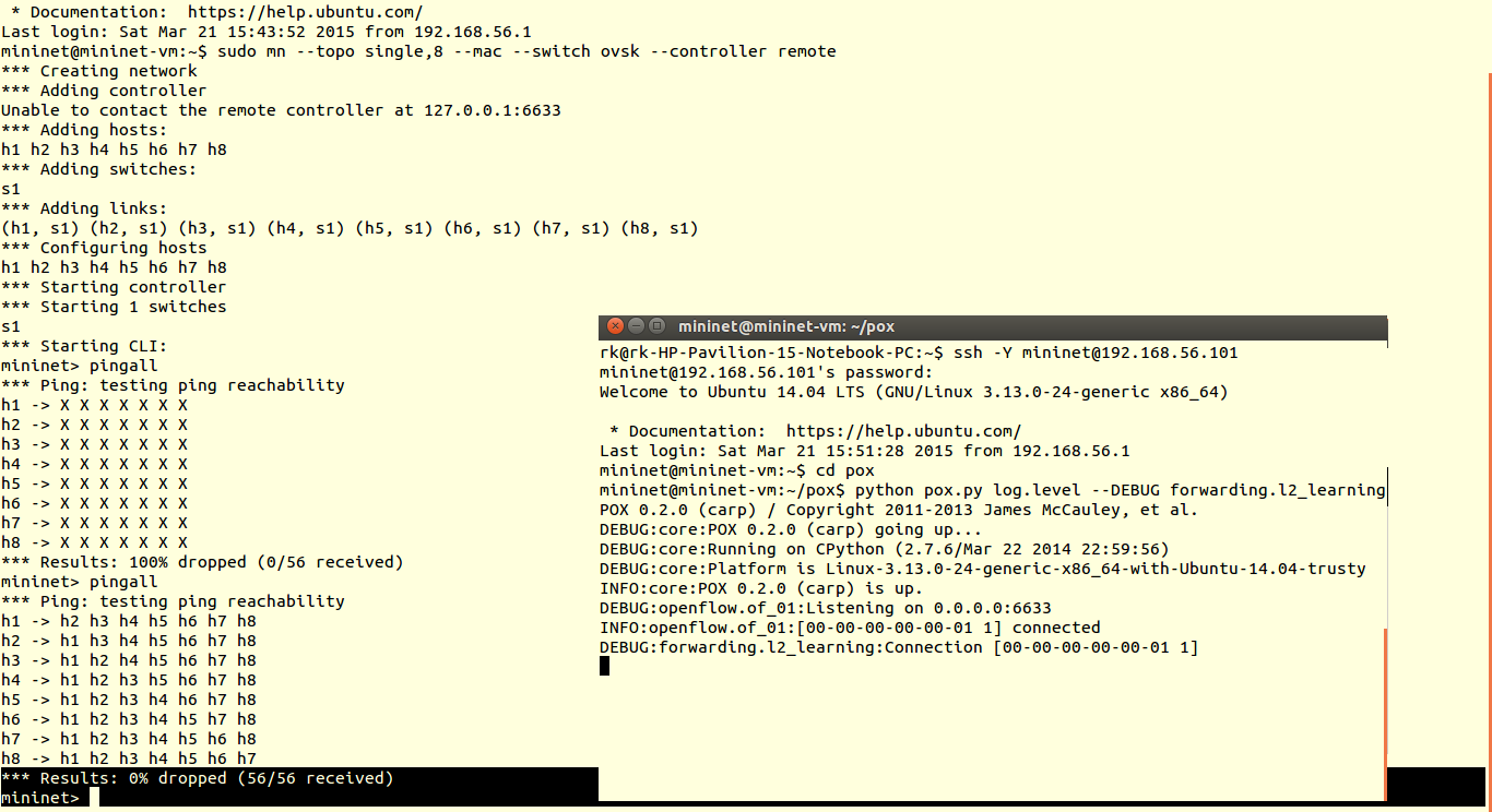
5) Then as usual save the scripts in pox/ext folder and run it

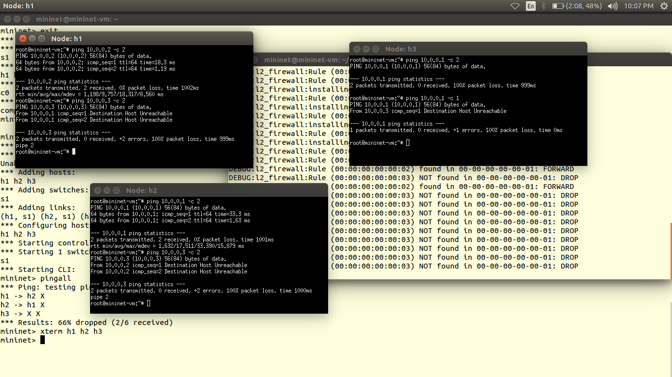
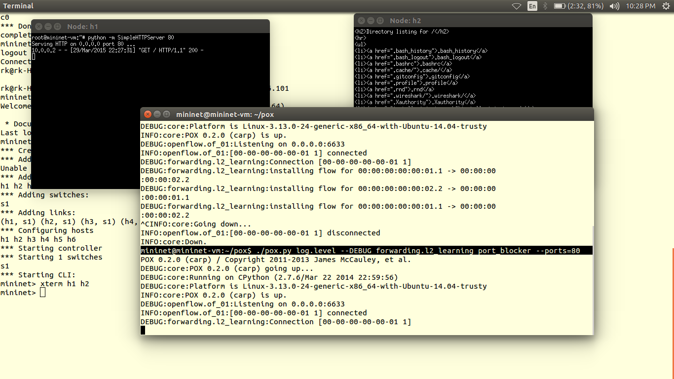
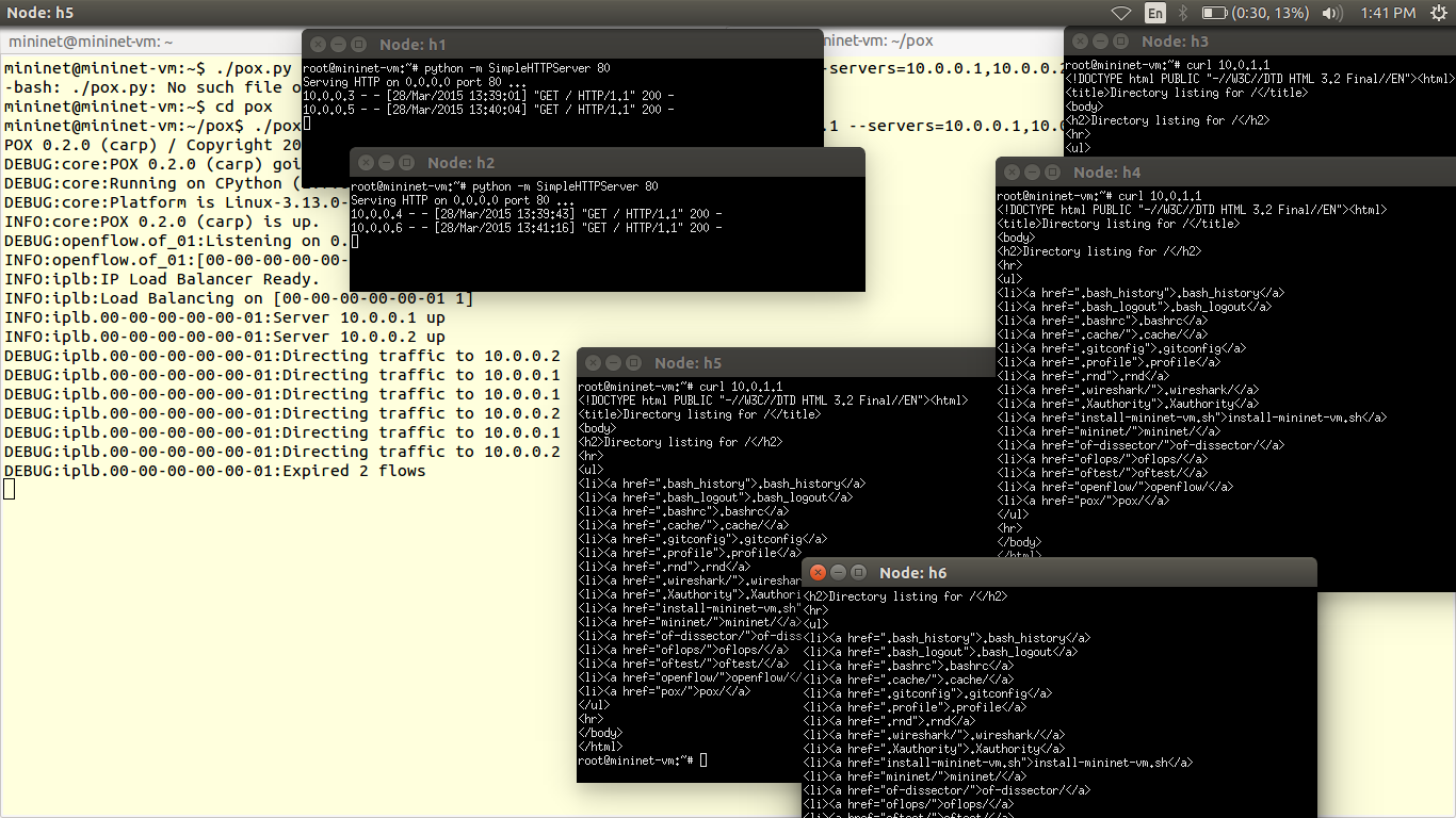
You can verify results using ping

This video tutorial will clear how to use VND.

Add custom flows with dpctl

Note: Google Drive links may not work or might be expired. You can find the scripts here

Tutorial no 10

                   DataPathController(DPCTL) is command line tool which sends OpenFlow messages to switch. Using this tool we get switch port and flow statistic also flow entries. We can also add flow rules in OpenFlowswitch using DPCTL. It’s very great tool to communicate switch directly without OpenFlowController.

In this tutorial, we use DPCTL to get flow status from switch and also we will learn how to add flow rule in switch using DPCTL.

1) Lets create a simple topology with one switch and 6 hosts.

>sudo mn – -topo single,6  – -mac – -switch ovsk – -controller remote

1

2) Now we will add flow rule for host1 and host2

dpctl add-flow tcp:127.0.0.1:6634 in_port=1, actions:output=2 

dpctl add-flow tcp:127.0.0.1:6634 in_port=2, actions:output=1

So data can be forwarded between port 1 & port 2 (i.e. Between host1 and host2)(Note:- You can choose switch instead s1 according to your topology. 127.0.0.1 is localhost IP since switch is inside mininet , it will be changed practically by switch IP address)

2

3) you can verify the flows installed in switch or not.

>s1 dpctl dump-flows tcp:127.0.0.1:6634

3

4) To check results we can use ping utility.

>pingall

Here we have connectivity between hosts 1 & 2 only, since we have added rule for port1 and port2 (i.e. host1 and host2)

4

5) Similarly you can add various flow rules using DPCTL without need of controller. Here I have listed some DPCTL commands

i) Manually shut up, shut down, flood, nonflood packets

>s1 dpctl mod-port tcp:127.0.0.1:6634 2 down    # down port no. 2

>s1 dpctl mod-port tcp:127.0.0.1:66343 up       # up port no. 13

>s1 dpctl dump-ports tcp:127.0.0.1:6634# gives physical port information, RX-TX  counters, error counters                                                                                                       

L2_firewall

Note: Google Drive links may not work or might be expired. You can find the scripts here

Tutorial no 8

L2_firewall

                        Firewall is security approach in networking. Design aspect of  firewall are according need of administrator. Here we are going to implement layer2 MAC based firewall which forwards only listed  MAC host’s packets and rejects other’s traffic. It is somewhat similar to NOX’s pyswitch in that it installs. POX does not contain firewall scripts. You can copy code or can download from here.

1) To save code of l2_firewall script, ssh into mininet and go to pox/ext. Open nano Copy and paste the code. Use key ‘CTRL+O’ to save code and ‘CTRL+X’ to exit nano editor. I have saved code with name l2_firewall.py

1

2

2) Now we will create topology with one controller one switch and 3 hosts.

3

We are going to forward packets of hosts with MAC 00:00:00:00:00:1, 00:00:00:00:00:2 and packets from other hosts (host3) are dropped.

Now let’s run firewall scripts which we have saved in pox/ext .

4

3) We can check results using pingall You can observe there is connectivity between host1 (00:00:00:00:00:1) and host2 (00:00:00:00:00:2) since we have allowed forwarding rule for the firewall script. Similarly we can change the MAC in the script and forward traffic or set layer2 firewall rule based on MAC address of devices.

5

4) You can also check ping result from indidual hosts using XTERM.

 6

 Credits: Firewall script from Nick Feamster’s coursera SDN course

Port_blocker

Note: Google Drive links may not work or might be expired. You can find the scripts here

Tutorial no 9

                            Portblocker is way to block TCP ports. For that we use a forwarding component which does fine-grained flows (e.g., l2_learning), and then intercept the PacketIn events. When you see a packet you want to block, kill the event.  This will keep l2_learning from seeing the event and installing a flow for it.

The source code for port_blocker is not in POX. You can copy following code or download from here. Save this code in pox/ext folder.

Here we will block port 80 i.e. HTTP port.

1) To save code of port_blocker script, ssh into mininet and open nano Copy and paste the code. Use key ‘CTRL+O’ to save code and ‘CTRL+X’ to exit nano editor. I have saved code with name port_blocker.py

1

2

2) Now we will create topology with one controller, one switch and 6 hosts.

3

3) We are going to block port 80. Lets first check port 80 is working. For that we will run simply l2_learning.py. We can use two hosts. On one host we run server and from second we request HTTP service by using curl utility(about curl installation refer IP_loadbancer tutorial)

4

Xterm h1 h2

Then on host1 run server by command

sudo python –m SimpleHTTPServer 80

On host2, request http service

curl 10.0.0.1

Here ip of host1 and host2 are 10.0.0.1,10.0.0.2 respectively.

6

Here you can see host2 getting HTTP reply from server (host1).

Now we will run our port_blocker.py script which is saved in pox/ext folder.

sudo python pox.py log.level –DEBUG forwarding.l2_learning port_blocker -–ports=80

 (Here you can change tcp port number)

7

So if host2 request service from host1(i.e. HTTP server), the packets are blocked. Observe the blocked packets on controller.

8

IP_Loadbalancer

Note: Google Drive links may not work or might be expired. You can find the scripts here

Tutorial no 6

                                     This component (which started in the carp branch) is a simple TCP load balancer. It takes a service_ip and a list of server IP addresses. And the http requests from different clients will be directed to different pre-defined http servers. The server is chosen based on round robin scheduling

                                       New TCP flows to the service IP will be randomly redirected to one of the server IPs. Servers are periodically probed to see if they’re alive by sending them ARPs. By default, it will make the first switch that connects into a load balancer and ignore the other switches. If you have a topology with multiple switches, it probably makes more sense to specify which one should be the load balancer, and this can be done with the -dpid command line option. In this case, you probably want the rest of the switches to do something worthwhile (like forward traffic), and you may have to create a component that does this for you. For example, you might create a simple component which does the same thing as forwarding.l2_learning on all the switches besides the load balancer.

1) Here to request service from HTTP servers we need utility curl. To install curl in mininet we need internet. We can connect mininet to internet using NAT interface eth1. Before that lets check eth1 has got an ip address or not using command.

ifconfig -a

1

Here you can see my eth1 interface has no IP address. We can get it from DHCP pool by using command

sudo dhclient eth1

2

Now you can verify it.

3

2)Now lets install curl                                                                                                                                               sudo apt-get install curl

4

3)We will create topology with 6 hosts with one controller and ofswitch.

5

4)To run ip_loadbalancer we need pass arguments.

./pox.py misc.ip_loadbalancer –ip=<Service IP> –servers=<Server1 IP>,<Server2 IP>,… [–dpid=<dpid>]

6

Let host 1 and host 2 are the http servers with IP addresses 10.0.0.1, 10.0.0.2 respectively. Also 10.0.1.1 is service IP address.

5)Now with help of xterm utility we get interface to hosts and servers. For that we use command                                                                                                                                                                     Xterm h1 h2 h3 h4 h5 h6

7

6) Now we run simple server on host1 and host2 on port 8080 [HTTP] using command python –m SimpleHTTPServer 80

8

Now we have started our servers.

7) Now other hosts can request service from 10.0.1.1

curl 10.0.1.1                                                                                                                                                            Observe the traffic pattern on servers (host1, host2) and on controller.

9

Overview

                     
Tutorial No.1

                       Here you will get hands-on experience on real SDN network. Here we will build simple Local Area Network (LAN) with SDN. Now recall our SDN architecture. To create LAN with sdn what we require-

1)Hosts

2)Data forwarding plane

3)Data controlling plane

4)Programing Interface

Untitled

1) Hosts :- Hosts are nothing but workstations/terminals among which we are going to create network (or LAN). We can use computer or mobile phone as host.

2) Data forwarding plane:- There are OpenFlow enabled switches available in the market but their set up cost is reasonable only for enterprise or campus level network at large scale. But we are creating LAN for experimental purpose or on very small scale to handle 6-7 hosts So we will use unmanageable router as our data forwarding plane. We are using TPLink 841 N (V9.0) router for this purpose. Its cost is near about $20-25. But TPLink has own firmware image installed in their devices. To make it OpenFlow enabled we have to change its firmware image(Unbricking). We will learn how to unbrick TPLink 841 N router in next tutorial.

3) Data controlling plane:- Job of the control plane is to match packet header field and instruct (install flow or rule in) forwarding plane about taking corresponding required action on packet. Hence our controller should capable to handle high packet data with good clock frequency, RAM, peripheral support, Ethernet support. For controller we have options like Raspberry Pi ,Intel’s Beaglebone, RouterBoard etc. We are going to use Raspberry Pi B+ as control plane in our LAN. And its cost is $35-45.

Raspberry Pi B+ Features:-

1)700 MHz clock

2)512 MB RAM

3)32 GB Expandable Memory

4)4 USB Ports, 1 Ethernet Port

5)SD card Slot

6)HDMI, Composite Video output

7)ARM7 processor

4) Programing Interface

As SDN promises directly programmable network, we should have to programing interface to our data & control plane. Control plane is itself Linux based platform so we can easily install our controller on it. We will use python based POX controller right now. In future we will also try for java, c, ruby, erlang etc. based controllers. And on data plane we will use open source embedded firmware OpenWRT. You will get more cleared in upcoming tutorials.

Therefore to design our SDN enabled Local Area Network we require,

1) Hosts:- Laptop, mobile phones or Tablets

2) Data forwarding plane:- TPLink 841N V9.0 with OpenWRT (OpenFlow1.0)

3) Data control plane:- Raspberry Pi B+ with POX

Estimate Cost of Setup is $55-70 (This cost may vary according to exchange rate of your country)

Note:-For testing and experiments purpose, you can use the openwrt devices listed here, whereas for testing/implementing in real network scenery on large scale, refer ONF vendor list having plenty of sdn SDN Controller, switches etc.

Screen Shot 2015-04-06 at 12.05.11

l3_learning

Note: Google Drive links may not work or might be expired. You can find the scripts here

Tutorial no 3

Testing layer 3 script l3_learning.py

                            Router is network intelligent device works on IP addresses unlike switch working on MAV address. Hence it is termed as intelligent than switch or hub. This component is not quite a router, but it’s also definitely not an L2 switch. It’s an L3-learning-switchy-thing. Perhaps the most useful aspect of it is that it serves as a pretty good example of using POX’s packet library to examine and construct ARP requests and replies.

                              l3_learning does not really care about conventional IP stuff like subnets – it just learns where IP addresses are. Unfortunately, hosts usually do care about that stuff. Specifically, if a host has a gateway set for some subnet, it really wants to communicate with that subnet through that gateway. To handle this, you can specify “fake gateways” in the commandline to l3_learning, which will make hosts happy. For example, if you have some machines which think they’re on 10.x.x.x and others that think they’re on 192.168.0.x and they think there are gateways at the “.1” addresses:

      We need hosts from different network. You can download script from here for topology of two hosts having IP 192.168.50.10, 192.168.10.10 i.e. from different network.

1) You can use nano editor to save the topology script in pox>ext location. Copy and paste the code in nano editor save using key ‘CTRL+O’ and exit editor by ‘CTRL+X’.

1

2

2) To run script

> sudo python ./mininet_script.py 3

3) Now run l3_learning script with fake gateways i.e. fakeways

4

4) Verify results using ping

h1 ping h2

h2 ping h1

6

 5

Environment setup

Tutorial no. 1      

              In this tutorial we will install the required software. For simulation part we are going to use Mininet. About platform, so it is recommended that use linux since no extra softwares are needed.

Pre-requisite:- Virtualbox installed.

1) Download mininet VM image from here. Extract it click on .ovf image & import vm image to virtualBox.

1

2

2) If you are running VirtualBox first time, you should make sure your VM has two network interfaces. One should be a NAT interface that it can use to access the Internet, and the other should be a host-only interface to enable it to communicate with the host machine. For example, your NAT interface could be eth0 and have a 10.x.x.x IP address, and your host-only interface could be eth1 and have a 192.168.x.x IP address. You should ssh into the host-only interface at its associated IP address. Both interfaces should be configured using DHCP. If they are not already configured, you may have to run dhclient on each of them, as described below.) Now let’s add network interfaces to VirtualBox. To add network interfaces use key “CTRL+G” .Add ‘NAT’ and ‘Host-only’ interfaces. You can also change DHCP pool address from here.

3

4

3) After this we will enable network adapter for mininet. Right click on mininet go to settings>>network and enable network adapter Now select adapter one for NAT and adapter 2 for host-only interface.

5

6

4) We have configured network settings for mininet. Double click on mininet to start            
Login        :- mininet
Password:- mininet

7

5) ifconfig –a

Will give ip addresses of interfaces. You can see my Host-only interface(eth0) got ip address but NAT (eth1) not got ip address.

8

Use this command to get ip for eth1 interface

  sudo dhclient eth1

9

6) We can use host only interface for ssh access of mininet.

ssh –Y mininet@192.168.56.101

Here ip address of host-only interface for my VM is 192.168.56.101

10


Mininet basics

Tutorial no 2

Basics of  Mininet

In this tutorial we will learn some basic commands of mininet.

sudo mn Create topology with two hosts, one OFswitch [openflowswitch] and one OFCTL[openflow controller]

net Shows ethernet link between nodes

dump Gives IP addresses and PID of nodes

nodes Available nodes in topology

pingall Ping reachability between hosts

2

L2 learning

Note: Google Drive links may not work or might be expired. You can find the scripts here

Switch is Datalink layer & intelligent device than hub. Unlike hub switch does not flood the packets in network. It learns MAC address of hosts and forwards the packets. We have default script l2_learning to check behaviour of switch in mininet.
1)We will use same topology used in last tutorial.
To create topology

sudo mn – -topo single,8 – -mac – -switch ovsk – -controller remote

{ sudo mn:- running mininet as root                                                                                                                 topo single,8:- topology with single switch & 8 hosts                                                                         mac:- mac is assigned according to hostnames by mininet                                                                         switch ovsk:- switch type is ovsk                                                                                                             controller remote:- controller running outside (remote)}

1

So we have single switch with one controller and eight hosts.
2) Lets check ping reachability using command pingall. We will not get connectivity since we haven’t run any script on controller.
2
4)Now we will run script for switch. Here we have to ssh again into mininet.
cd pox

sudo python pox.py log.level –DEBUG forwarding.l2_learning

And you can see we got connectivity between hosts.
4
5)To see mac learning results we are going to use xterm and tcpdump utilities.
xterm h1 h2 h3
this command will give us windows for hosts
sudo tcpdump –XX –i h1-eth0 sudo tcpdump –XX –i h2-eth0
This will allow host to see ping reply Our host has ip addresses

10.0.0.1

10.0.0.2

10.0.0.3

.

.

10.0.0.8
Let’s ping host2 from host3
5
ICMP echo request is send to all hosts in network. But you can see only host1 gives ICMP echo reply .Also on controller side you can observe MAC addresses are learned .